How to make a serial cable for CAS PD-II Scale (DIY)
We could not find many reliable references out there on how to make a serial cable CAS PD-II.
This post covers how to build your own serial cable to integrate CAS PD-II scale with MiPOS Software. Refer this link to how to set up the software after successfully connecting the hardware together.
* Information we provide here may be different from the information provided by the manufacturer.
It is always recommended to source the original cable from the Supplier for CAS PD-II Scale. The cable does not come in the box and needs to bought separately. Majority of the Scale Integrations for inhouse projects are tested before delivery, so customers only need to plug the cables with no setup required onsite.
This information is useful for someone trying to Integrate a CAS PD-II with MiPOS Software, supplied from a different source.
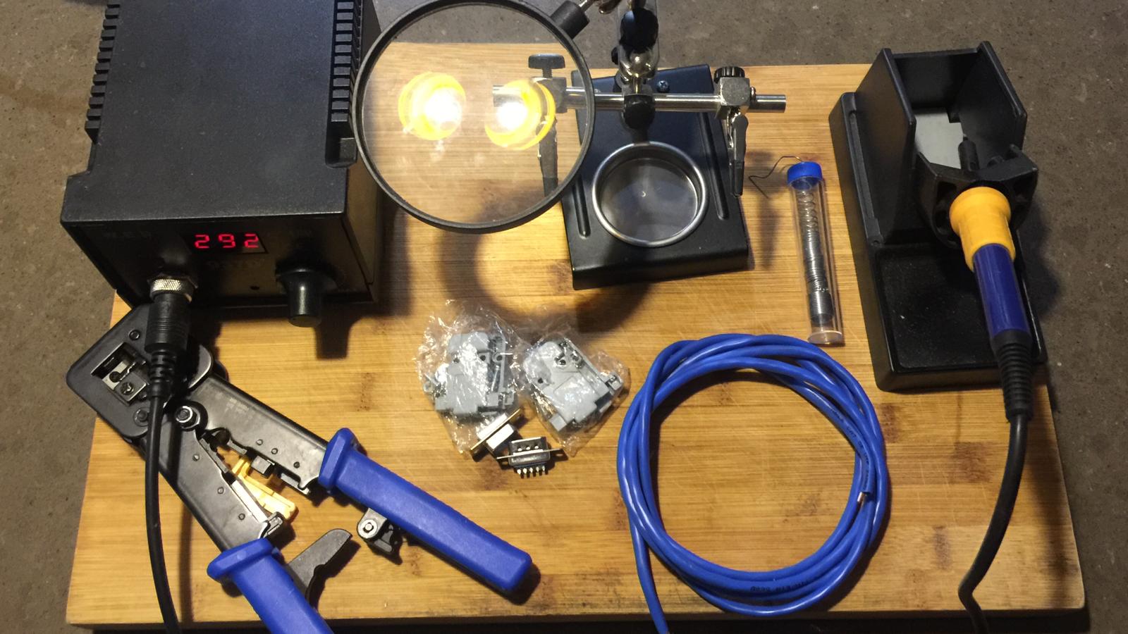
Things you need

How to make a Serial Cable for CASH PD-II Scale
Test your COM Port on POS Terminal or PC
1. Once you decide on which COM port to use, or the Virtual COM Port via USB to Serial Converter, Make a 9 pin D-Sub DB9 PCB Connector buy short pin 2 and pin 3. This is the easiest method for testing a COM Port.
UniTek (Prolific Driver) – $12.95 AUD
https://www.ebay.com.au/itm/USB-to-RS232-DB9-9Pin-Serial-Cable-Adapter-Converter-Windows-Win-10-Mac-Android/401118157257
UGreen (Prolific Driver) – $14.55 AUD (1m). Also available in 1.5m/2m/3m. GOLD pins
https://www.aliexpress.com/item/32611514539.html (RS232 Male Round Gold)
StarTech (Prolific Driver) $19.44 AUD

9 pin D-Sub DB9 PCB Connector – Short Pin 2-3 for Serial Port Testing
2. Install Putty. Or Hyper Terminal if you have access to this software. But we use Putty for simplicity.
3. Configure Putty as the following information and OPEN to connect.
COM1 – Select the Com Port
Speed (Baud) – 9600
Data bits – 7
Stop bits – 1
Parity – Even
Flow control – None
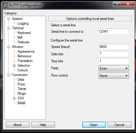
Putty Serial Settings

Putty Serial
4. Test your COM port buy typing few Keys, you should see your Keys displayed if the COM Port is working.

Serial Feedback
** If you don’t get any feedback, try different COM Port. Check if you have short pin 2-3 together. This is a simple process, so you can’t go wrong.
Now, let’s make the cable.
Building the Serial Cable is a little complex task if you are new to soldering. But unfortunately, there’s no other way. We found to make other suggested cable configurations on the internet. It’s confusing because, none of them worked for us, even the one on Product Manual. This configuration is what we use in our Scale Integration.
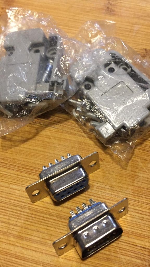
9 pin D-Sub DB9 PCB Connector – RS232 Serial Solder Type
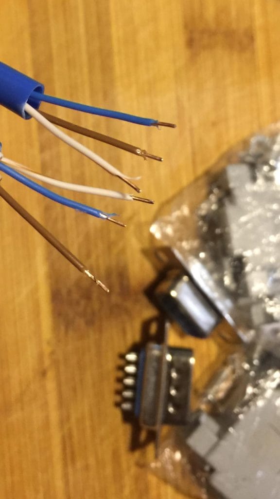
1.5M Network Cable with 3 wires ready for soldering
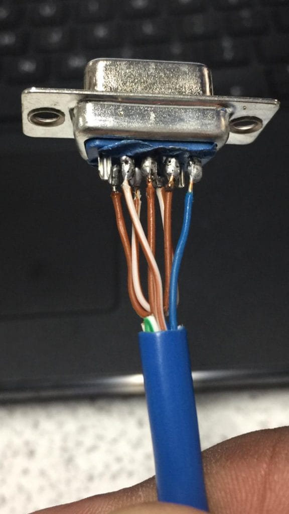
9 pin D-Sub DB9 PCB Connector – Computer Side
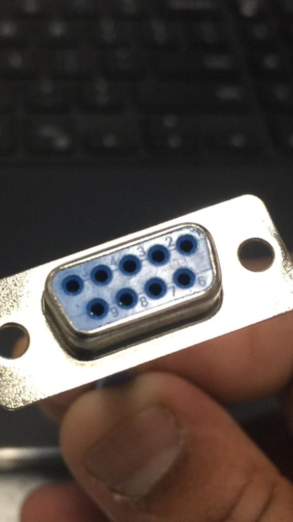
9 pin D-Sub DB9 PCB Connector – PINS
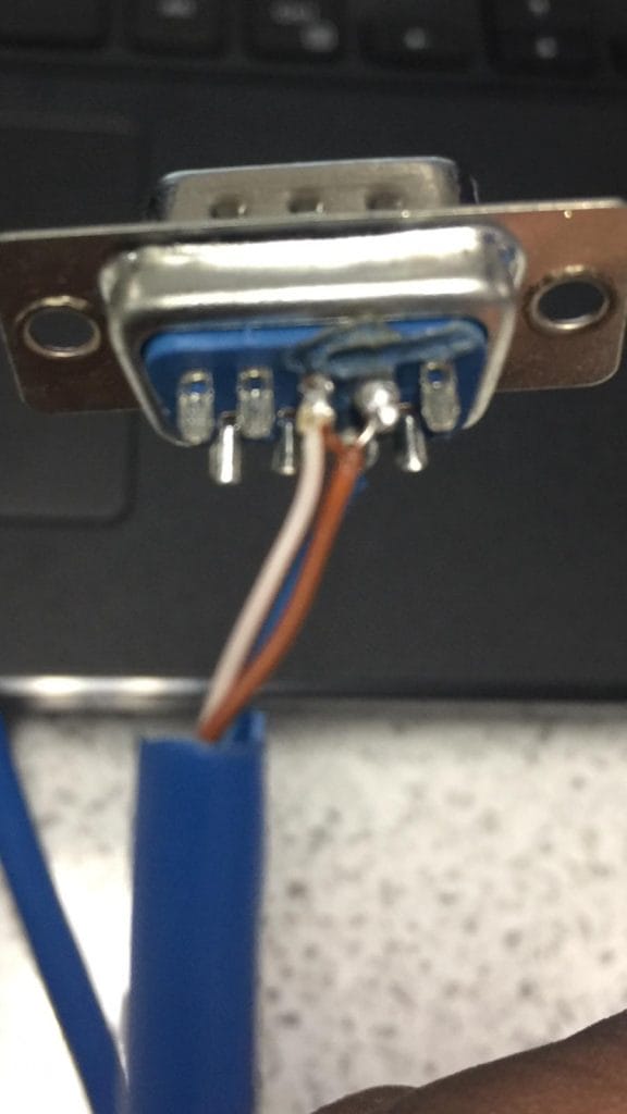
9 pin D-Sub DB9 PCB Connector – Scale Side
PC Side of the Serial Cable also be constructed using RJ45 Socket

CAS PDII Serial Cable POS Side in RJ45

CAS PDII Serial Cable POS Side in RJ45 – Pin Diagram
This is how your 2 connector ends should look like.
Crossover pin 2-3
Ground Pin 5 – Pin 7
Pin 4-6
Pin 7-8

CAS PD-II Serial Cable Pin Diagram
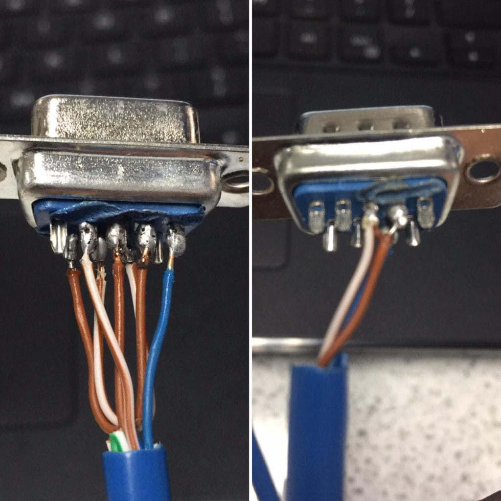
9 pin D-Sub DB9 PCB Connector – After Soldering the Cable
Select CAS PD-II Scale mode to Type-2

CAS PD-II Type-2
If you have tested the COM port, created the serial cable and change the Scale mode, you are good to go ahead and setup MiPOS Software to integrate with CAS PD-II Scale.

